


One-stop Metal Chips Briquetting Machine Factory in China
Installing a metal chips briquetting machine correctly is critical for its performance, safety, and longevity. A poor installation leads to vibration issues, misalignment, premature wear, and potential equipment failure. This guide covers the essential steps for proper foundation preparation and workshop setup.
Machine & Site Specifications Review
Obtain Foundation Drawings: The manufacturer must provide detailed foundation layout drawings, including anchor bolt locations, dimensions, and load specifications (static and dynamic).
Verify Key Data:
Machine Weight: Total weight of the machine (including the hydraulic power unit).
Dynamic Load: Forces generated during compression (both vertical and horizontal).
Footprint Dimensions: Exact length, width, and height of the machine base.
Workspace Audit: Ensure you have:
Adequate Clearance: Space for operation, maintenance (e.g., removing the main cylinder), and material flow (chip conveyor in, briquette conveyor out).
Access for Installation & Future Service: Door width/height for machine entry. Consider overhead lifting points (jib crane, hoist) for servicing heavy components.
Utility Points: Proximity to required 3-phase electrical power, compressed air (for controls, if needed), and coolant drainage (for the fluid collection tank).
A proper foundation is the single most important factor for a stable installation.
Key Foundation Criteria:
Load-Bearing Capacity: The factory floor or dedicated foundation must support 1.5 to 2 times the total machine weight to account for dynamic forces. This typically requires a reinforced concrete pad.
Minimum Concrete Specification: 3000 psi compressive strength or higher, as specified by the manufacturer.
Minimum Thickness: At least 6 inches (150mm), but often 12-18 inches for larger machines. It must be isolated from the general floor slab to prevent vibration transmission.
Levelness & Flatness: The mounting surface must be perfectly level and flat within the manufacturer's tolerance (often ±0.5mm/m²). Use a precision level during pouring and finishing.
Anchor Bolt Installation: This is a precision task.
Method: Use anchor bolt templates (supplied by the manufacturer) or embedment sleeves (for greater placement tolerance). Bolts must be grade 5 or grade 8.
Alignment: Bolts must be perfectly vertical and positioned accurately according to the drawing.
Curing: Allow the concrete to cure fully (typically 7-28 days, depending on mix) before applying any load.
Vibration Damping (Optional but Recommended): For installations on upper floors or in vibration-sensitive areas, consider anti-vibration pads or grout compounds (like epoxy or non-shrink cementitious grout) poured under the machine base after alignment.

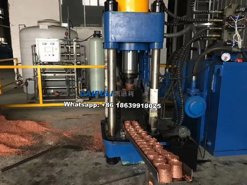
Step 1: Positioning & Placement
Use a forklift or overhead crane to carefully position the machine over the anchor bolts.
Lower it gently, guiding each bolt through the baseplate holes.
Step 2: Leveling & Alignment
Place precision leveling pads or shims under the base at all support points.
Using a precision machinist's level, adjust the shims to bring the machine to perfect level in both directions (front-to-back and side-to-side).
Critical Check: The main compression chamber and ram must be perfectly plumb (vertical). Misalignment here causes severe side-loading and rapid seal/cylinder wear.
Step 3: Securing & Grouting (The "Final Lock")
Tighten Anchor Nuts: Once leveled, uniformly tighten the anchor nuts to the specified torque.
Grouting: If specified, pour grout into the cavity between the baseplate and the foundation. This provides 100% uniform load bearing and prevents shifting. Follow the grout manufacturer's instructions for mixing and curing.
Step 4: Hydraulic & Electrical Connection
Hydraulic System:
Connect the hydraulic power unit (HPU) to the main cylinder via clean, high-pressure hoses.
Fluid: Fill the reservoir with the correct ISO-grade hydraulic fluid (typically ISO 46 or 68). Use a filter cart when filling to ensure cleanliness.
Electrical System:
A licensed electrician must connect the machine to the correct 3-phase power supply, matching voltage and amperage requirements.
Install a main disconnect switch within sight of the operator.
Ground the machine properly according to local codes.
Step 5: Peripheral System Integration
Feed System: Connect the chip conveyor or feed hopper. Ensure the feed rate matches the briquetter's cycle time to avoid overfeeding.
Coolant/Drainage System: Connect pipes from the machine's fluid drain port to your coolant recovery tank or waste oil containment system. Never let fluid drain onto the floor.
Briquette Handling: Plan for a conveyor, chute, or collection bin to handle the ejected briquettes.
Pre-Start Inspection: Verify all guards are in place, fluid levels are correct, and no tools/obstructions are in the machine.
Dry Run (No Load): Run several cycles with no material. Listen for unusual noises, check cylinder movement for smoothness, and verify control functions.
Load Test: Run the machine with clean, dry chips. Start with a partial feed, gradually increasing to full capacity.
Monitor hydraulic pressure and temperature.
Check the quality and density of the first briquettes.
Operator Training: Train all personnel on:
Safe startup/shutdown procedures.
Daily inspection points (fluid leaks, loose bolts).
How to clear a jam (always following Lockout/Tagout - LOTO).
Basic troubleshooting (e.g., low briquette density, slow cycle time).


